THE IMPULSE TRANSMITTER.
AKA THE MASTER CLOCK.
In the ” Pul-syn-etic ” System of Electric Impulse Clocks is embodied the experience of over 30 years.
The ” Pul-syn-etic ” Time Transmitter which gave the lead in Modern Time Transmitter construction is-Imitated but not Excelled.
We were first in 1904 to employ the roller on incline plane for giving the half-minute constant gravity impulse to Pendulum. Up to our introducing this feature, if for any reason the pendulum failed, due to a weakening current, the battery ran down through the contacts.
TRANSMITTER SPECIFICATION.
CASE.
Of designs illustrated, in sound well-seasoned hardwood, properly finished and polished. Full length front glazed panel A forming door with strong hinges, auxiliary bolts, and lock and key.
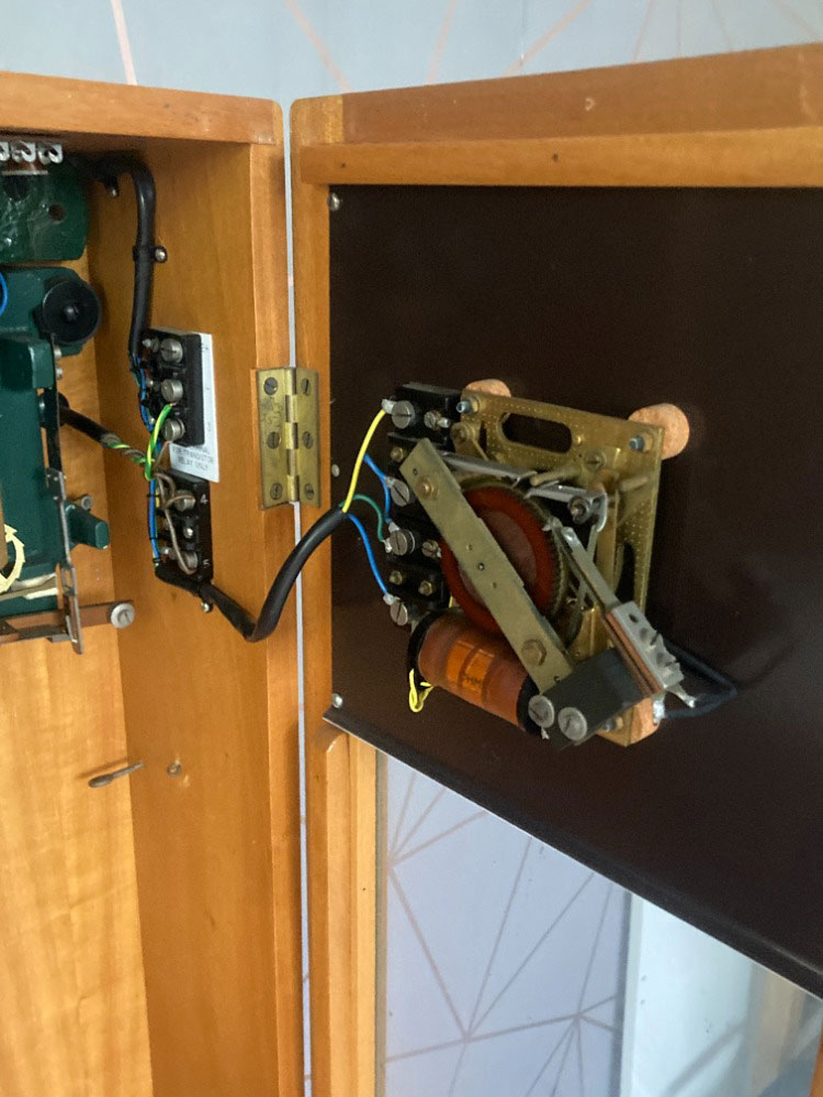
MOVEMENT.
Formed of rigid cast-metal bed plate, with correctly proportioned electro-magnet, improved quick-break sparkless half-minute automatic adjusting impulse contact, with heavy platinum-silver surfaces, escapement and repeating mechanism robustly constructed on Standard Clock Makers’ principles. Inclined plane gravity impulse mechanism giving constant drive independent of battery strength and variation of circuit. Hardened steel arbors working in suitable bearings. Seconds Pendulum Fully Compensated. Rod of “Si-ne-var ” non-expanding alloy (coefficient of expansion 0.0000008 per I ·q. Heavy steel cylindrical bob and toothed rating nut, each tooth representing approximately one second per day adjustment, and Platform for Regulating Weights. All guaranteed capable of being regulated to keep time within one second per day, plus or minus.
Half this small error is often obtained by careful regulation in position,
TRANSMITTER OPERATION.
The Pendulum of the Transmitter is kept in vibration by absolutely constant mechanical impulses imparted to it at halfminute intervals by a weighted lever termed the Gravity Lever (see Diagram C519).
The Gravity Lever is provided with a Roller which rolls down the Inclined Face.of the Impulse Pallet, thus giving the Pendulum Crutch a gentle push.
This continues until the Contact pieces meet, when the Electro-Magnet is energised by the flow of current through it.
The Armature is attracted and at once replaces the Gravity Lever on to the Stirrup Catch. Meanwhile the Clocks which are connected in circuit with the Battery are
advanced half-a-minute.
The action is brought about in the following manner :
The Pendulum Crutch in vibrating, carries with it the Driving Pawl which pushes around the ‘Scape Wheel tooth-by-tooth. The Back Stop Click prevents Its backward
movement.

At each complete revolution of the ‘Scape Wheel (which occurs every half-minute), the Driving Pawl engages a Deep Tooth and its right hand extension, instead of passing through the Stirrup, engages the Stirrup Catch just above the Stirrup, pushing the Stirrup catch and releasing the Gravity Lever.
The Roller drops on to the dead face of the Impulse Pallet, then runs down the inclined Face, giving it an Impulse. Contact
is then made as above described for the dual purpose of operating the Impulse Clocks and replacing the Gravity Lever.
The Guard shown just above the driving pawl prevents two teeth being taken by the driving pawl in case the Pendulum swing is exaggerated by any means.
ADVANCE LEVER.
An advance lever with cord is fitted to the movement, by which all impulse clocks in the circuit can be advanced one impulse every two seconds when required, as for instance in Daylight Saving change,
THE CONTACTS.
As detailed on page 4 the contacts indirectly serve the dual purpose of energising the pendulum and impulsing the clocks.
The Contacts are fitted with an anti-spark device and experience has shown that they have a life of many years without attention.
Reproduced herewith is an actual oscillograph record of W the half-minute impulse which is passed through all the clocks.
Note the low current consumption and the short period of contact which means a saving of Battery Power.
CURRENT CONSUMPTION.
In the “Pul-syn-etic” System this is negligible-see the oscillograph curve above. The setting figure is0.22 amp., while the operating figure is only 0.18 amp. for I/20th sec. every half minute.
FITTINGS.
Substantial terminals, and fixing plates for four fixing screws are provided.
DIMENSIONS.
Size overall, 53-in. x 13-in, x 8-in. ; weight, without time dial, approx. 44 lbs, Fig. C37 slightly exceeds these dimensions and weight.
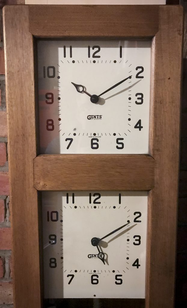
NOTE.-The three Transmitters shown on page 7 at Figs. C6, C7 and C37 are identical except that the latter two have a time dial with its impulse movement fitted on the door of the case. The Transmitter mechanism is fully visible on opening the door.
For positions where a time dial separate from the Transmitter is desired, the Fig. C6 type is recommended.
NUMBER OF CLOCKS IN CIRCUIT.
A “Pul-syn-etic ” Transmitter will impulse any reasonable number of Impulse Clocks.
We have installations where over 100 are on one Circuit controlled by one Transmitter. It should be remembered however, that the Voltage of such a circuit is high, and it is this voltage and the responsibility of having so many clocks
in one circuit in case wires are carelessly cut, that is the controlling factor. We particularly draw ·your attention to pages 36 and 37-Sub-Transrnitters and Sub-Transmitting Relays.
BATTERY POWER.
The simplicity of this is dealt with independently on pages 39, 40, 41 and 42. Where Service Mains are available, the ” Pul-syn-etic ” System may be termed Mains operated, without the disadvantage that should such mains fail, all clocks are rendered inoperative.
For full details of ” See-Saw ” and Observatory Control,-see Book 5, Section 4.

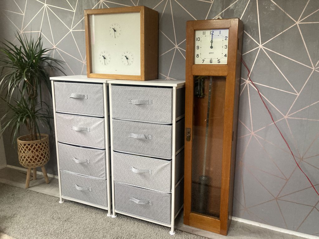
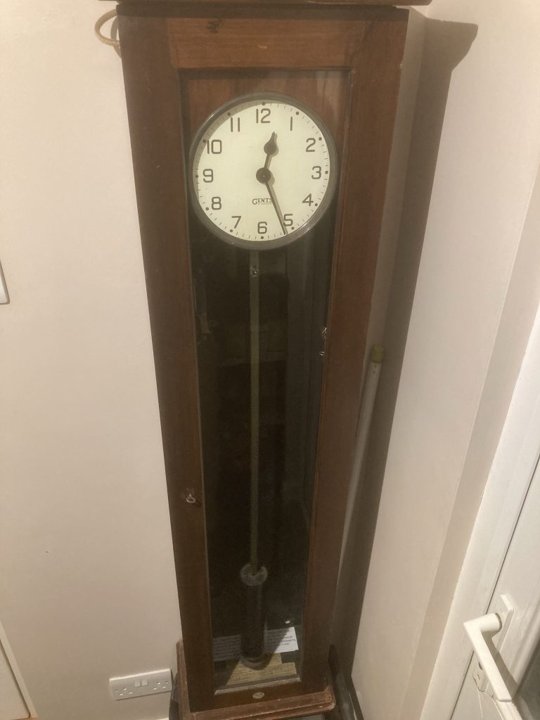
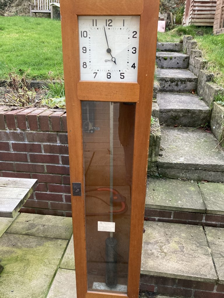
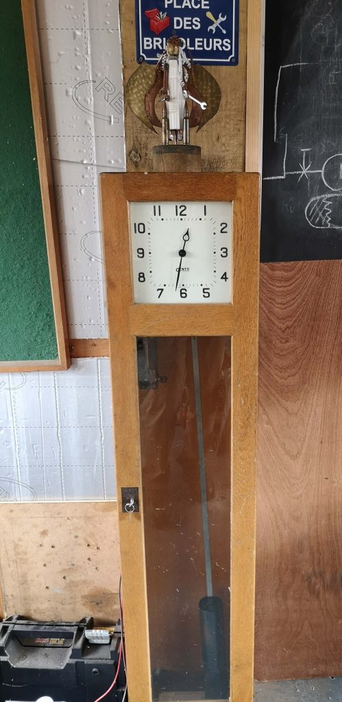
FIG. C6 TRANSMITTER.
In polished Teakwood case with glass front panel, door secured with substantial hinges, auxiliary bolts, lock and key, giving access to movement and pendulum. Substantial fixing plates and alignment studs to enable case to be fixed in a vertical position, complete with current balancing adjustable resistance (To Specification on pages 4 and 5).
PRICE, each £15
CODE WORD: zilik (E)
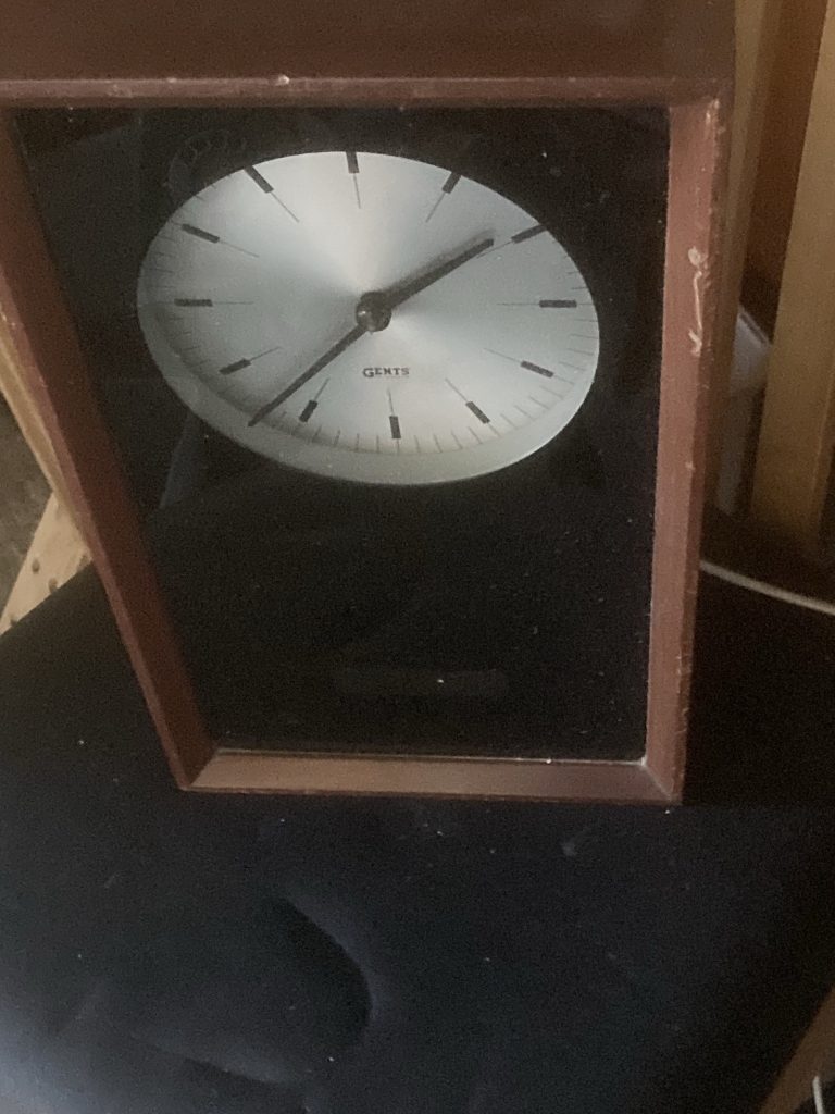
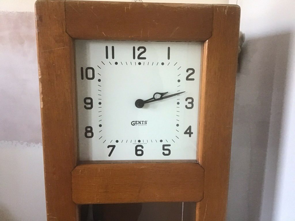
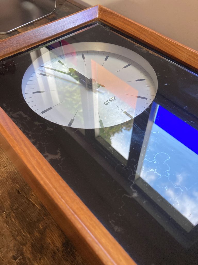
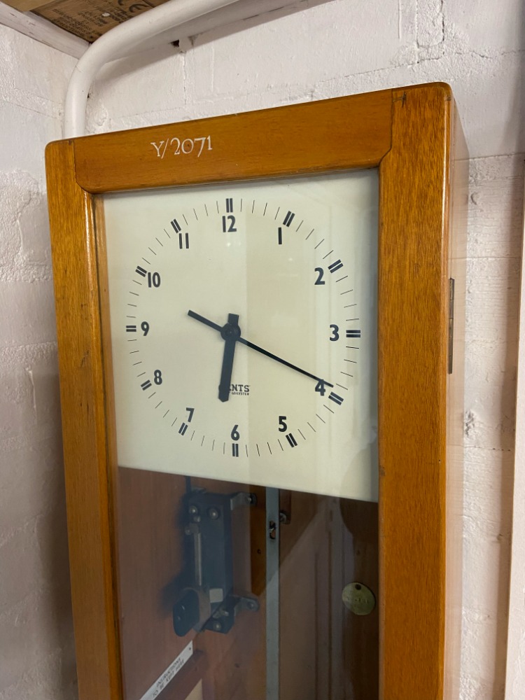
FIG. C7 TRANSMITTER.
Generally as Fig. C6 above, but with 7-in. time dial.
PRICE, each £17
CODE WORD: zilje
FIG. C37 TRANSMITTER.
Generally as Fig. C6 and C7 but in Ornamental solid hardwood case, highly finished,
PRICE Without Time Dial, each £19
CODE WORD: zillo
PRICE With Silvered Time Dial, as illustrated, each £22
CODE WORD: zilny
Products in circulation today
Gents’ of Leicester C7 30 second and 1 Minute Impulse Master Clock
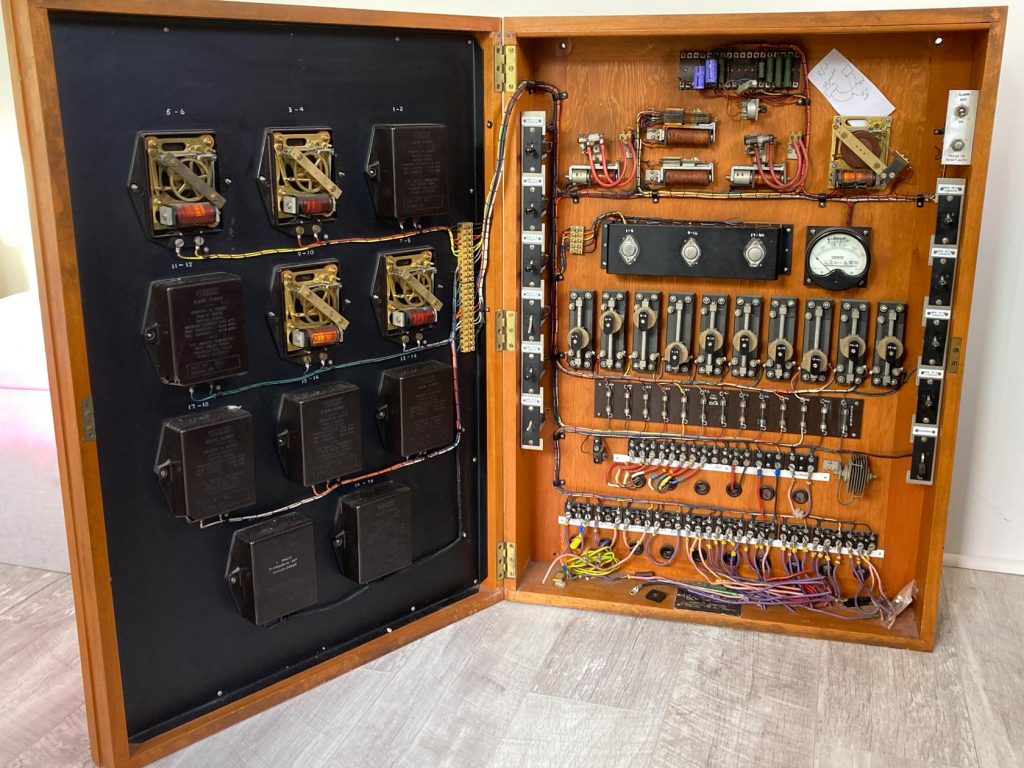
Two Master Clocks and Distribution Board removed from (old) Scotland Yard before they turn it into a hotel.
GENTS’ Garage Network