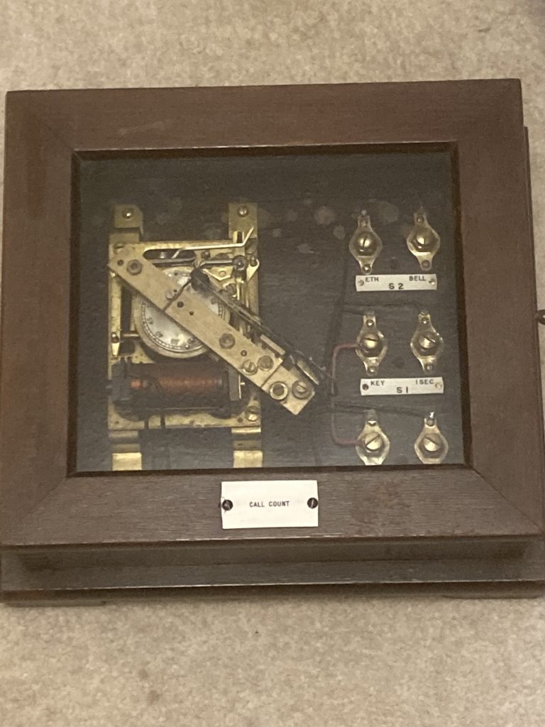
SUB-CONTROL TRANSMITTER.
SUB-CONTROL OF GROUPS OF IMPULSE CLOCKS.
The Standard “Pul-syn-etic” Transmitter is actually capable of controlling, not only an installation of 50 or even I00 Impulse Clocks, but also of dealing with scattered buildings over a large area, such as are found in some modern works. The “Transmitter” will control all the Public Clocks for example in a large city in a similar manner, by the use of Sub-Transmitters.
In any such large area however, or where there are a large number of Impulse Clocks, it is desirable, on account of risks to lines–often fixed overhead-to isolate the Installation into a number of Sub-circuits. This procedure also ensures that the voltage on the circuit is not unduly high, if the System as a whole is large.
All Sub-circuits or groups are controlled by one Transmitter-the “Prime Transmitter.”
The individual sub-circuits are then dealt with by means of either Sub-Transmitters or Sub-Transmitting Relays as below.
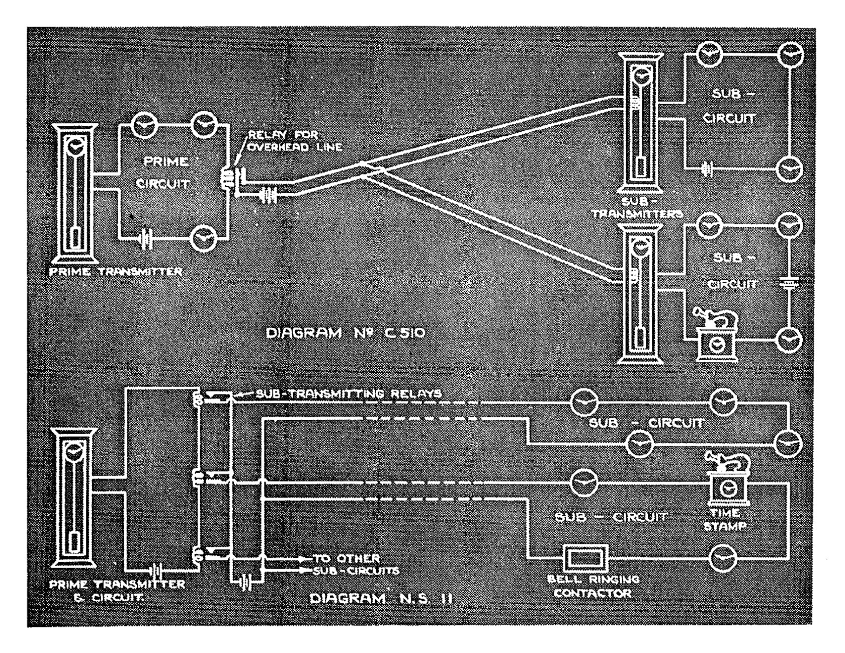
“A”-By means of Sub-Transmitters which consist of a Standard Transmitter with its Pendulum governed by “Reflex Control.” Diagram CS 10-page 37.
“B”-By mean of Sub-Transmitting Relays. Diagram NSI I-page 37.
With System “A” using Sub-Transmitters, a Prime Transmitter is employed, and in its time circuit, in addition to the usual Impulse Clocks, is inserted a Reflex Control, fixed in the Case of, and controlling the Pendulum of, another Transmitter. This second Transmitter then becomes what is known as a Sub-Transmitter.
If therefore, the circuit of the Sub-Transmitter is interrupted, it will affect only the Clocks in that circuit, and not the Prime circuit. Conversely, should the Prime circuit be interrupted, the Sub-Transmitter circuit will be virtually unaffected, although ungoverned for the time being.
Where overhead lines are being employed, we strongly advocate the use of Sub-Transmitters. Rather than carry the Prime Time Circuit overhead, a Sub-Transmitter is employed to control the other section, and a Fig. CI06 Overhead Line Relay is inserted in the Prime circuit. (See diagram CSI0 on the opposite page).
The Sub-Transmitters, by means of Reflex Control, are under the direct control of the Prime Transmitter, as far as time keeping is concerned. Should a break however occur in the overhead lines, these Sub-Transmitters carry on, although ungoverned, and the circuit is not interrupted.
The purpose of the overhead line Relay, which is placed in the Prime circuit, is to prevent damage to overhead lines interrupting this Prime circuit also. It will be seen that in a layout of this nature, even although all overhead lines be carried away, the three circuits remain virtually unaffected.
With System “B” employing Sub-Transmitting Relays, the operation is generally the same. It will be observed however, that with this scheme, failure of the sub-circuit overhead lines-if any-will certainly interfere with that particular Sub-circuit, but with no other.
It is also usual, again to prevent interference, to localise the Prime Circuit as far as possible. With these points in mind, System ”B” is to be strongly recommended on the score of simplicity and ease of supervision.
For the sake of clarity, 2 Batteries are shown in Diagram NS 11, page 37, but it will be appreciated that one central Battery will suffice.
It is suggested that the layout of an Installation is dependant upon the proportion of Clocks in each group and upon the geography of the building, or buildings which are to be served, and we are only too pleased to advise.
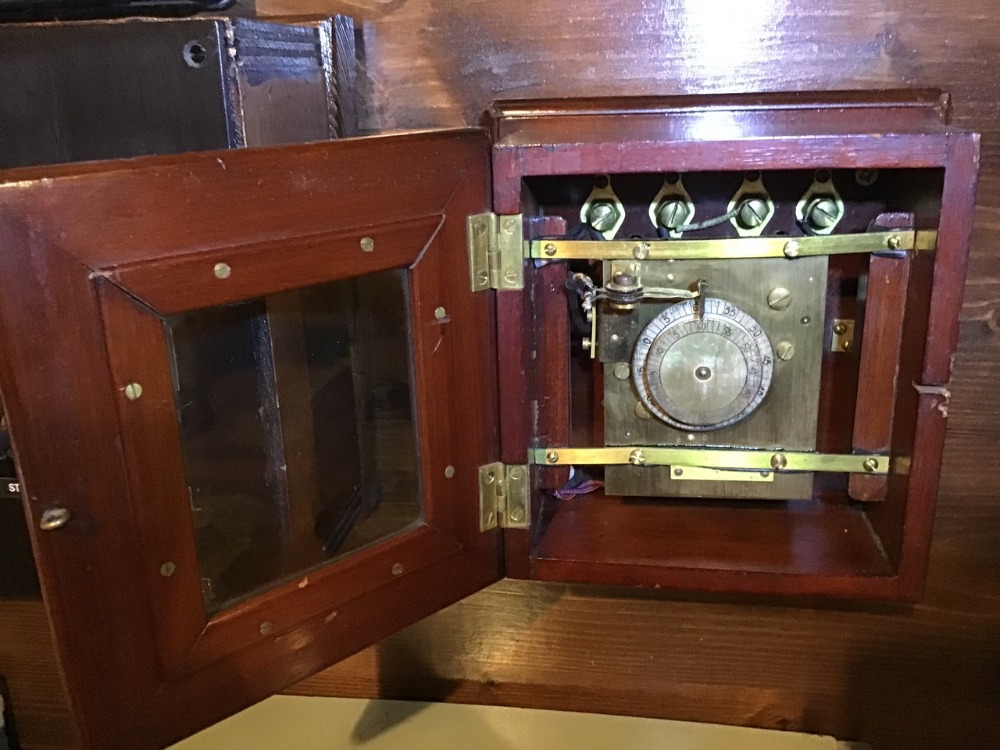
SUB-TRANSMITTERS
SUB-TRANSMITTER (System A, page 36)
“Reflex Control,” as Fig. CI04, page 38, fitted to the pendulum of any standard Transmitter, rendering it thereby a Sub- Transmitter to operate as System “A,” Diagram CSIO.
PRICE, each: Add to price of Transmitter chosen £5 • 12 • 6 Code word zoeln (E)
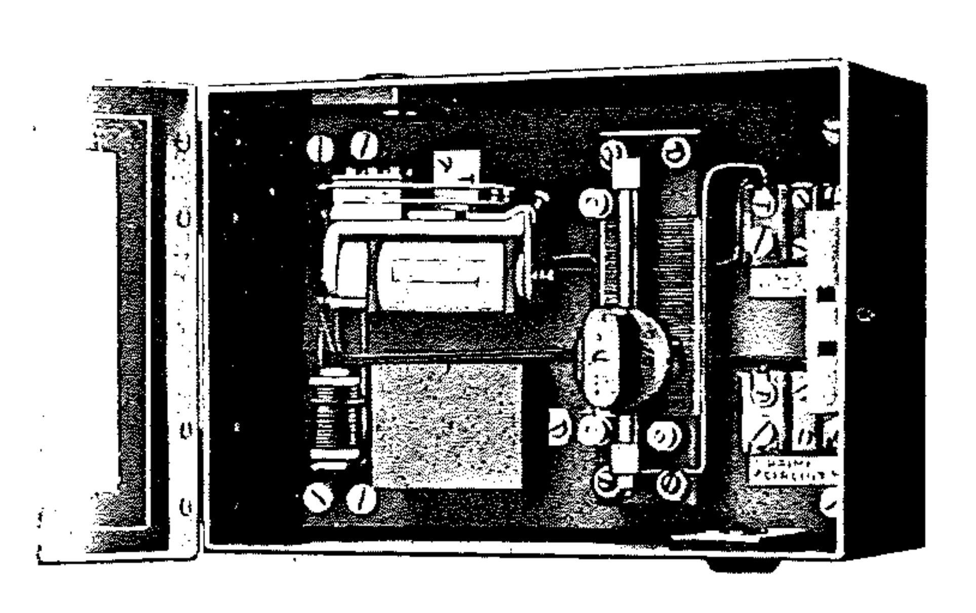
FIG. C63 SUB-TRANSMITTING RELAY (System B, page 36).
For impulsing a Sub-Time Circuit. Special Relay ·with heavy platinum-silver contacts, condenser resistance anti-spark device, variable resistance for current adjustment, the whole enclosed in metal case with glazed front. The Relay is so constructed that the current in the Sub-Circuit has a slightly longer duration than that of the Time Circuit operating it.
To operate as System “B”, Diagram NSI I.
For use when required for guarding Prime Transmitter Time Circuit, as shown in Diagram No. CSIO above.
PRICE, each: £4 • 4 – 0 Codeword: zoebd
FIG. CI06 OVERHEAD-LINE RELAY
For guarding Prime Transmitter Time Circuit, as shown in Diagram No. CSIO above.
Specification and illustration generally as Fig. C63 above.
PRICE, each: £5 • 4 – 0 Codeword: zoecf
C63
Products in circulation today